Analysis of load data for developing a self-propelled underground crop harvester during potato harvesting

ENGINEERING
Min Jong Park1Seung Min Baek2Seung Yun Baek2Hyeon Ho Jeon2Wan Soo Kim3Ryu Gap Lim4*Yong Joo Kim1,2*

Abstract

The purpose of this study is to develop a self-propelled underground crop harvester and its performance was evaluated by measuring the load during actual potato harvesting operations. This study was conducted at a constant working speed of 1 km·h-1. A load measurement system was installed to measure the actual load and the required working power was analyzed. A hydraulic pressure sensor was also installed to measure the hydraulic pressure. The required hydraulic power was calculated using the hydraulic pressure and flow rate. The results showed that the engine speed, torque, and power during harvesting operation were in the range of 845 - 1,423 rpm, 95 - 228 Nm, and 9 - 31 kW, respectively. Traction power, excluding the hydraulic pump of the tractor and power take-off (PTO) output, was in the range of 9 - 28 kW, and it was confirmed that it occupies a ratio of 16.2 to 50% of the engine rated output. The engine can supply the minimum required traction power to move the vehicle. This means that the engine used in this study could be down-sized to be suitable for an underground crop harvester. In this study, the gear stages of the tractor were not considered. This research thus shows the possibility of developing a self-propelled underground crop harvester.

Keyword


Introduction

전 세계 인구가 증가함에 따라 농업 생산성 증대에 대한 필요성이 대두되고 있다. 국내 농업 기계화율은 벼농사의 경우 지속적으로 증가하여 2020년 기준 98.6%에 달하지만, 밭농사의 기계화율은 61.9%에 불과한 것으로 나타났다(KOSIS, 2021a). 이는 수확 작물의 종류가 한정된 논농업에 비해, 밭 농업은 재배 작물의 종류가 다양하여 기계를 작물 맞춤형으로 제작하는 데에는 한계가 있기 때문이다(Suh, 2021). 밭 농업 작업 중 경운·정지 및 방제작업은 기계화율이 90% 이상이나, 파종·정식 및 수확작업은 대부분 인력에 의존하고 있어 고령화·여성화 되고 있는 농업인구에 큰 부담이 되고 있다(Kim et al., 2020; KOSIS, 2021b). 따라서, 밭 농업 기계화율의 제고를 위해 수확 작업의 기계화에 대한 연구 개발이 활발하게 진행되고 있다. 밭 농업 중 감자와 같은 땅속 작물의 수확 작업은 노동부하가 크며 이를 줄이기 위해 땅속 작물 수확기를 사용하고 있다. 그러나, 현존하는 땅속 작물 수확기는 대부분 트랙터 부착형으로 개발되었으며, 트랙터 부착형 땅속 작물 수확기는 기체가 크며, 트랙터에 부착되면 길이가 길어 크기, 선회반경, 현장 적응성 문제 등으로 인해 소규모 재배 농가가 많은 국내 환경에 적합하지 않다. 따라서 국내 농업 환경에 맞는 자주식 땅속 작물 수확기에 대한 수요가 증가하고 있다(Lee et al., 2020). AVR (벨기에), ASA-LIFT (덴마크), GRIMME (독일), Sanei Industry (일본) 등의 해외 선진사에서 자주식 땅속 작물 수확기를 개발한 사례가 있으나, 이들은 대부분 대규모 재배에 적합한 형태로 국내 토양환경 및 소규모 재배형태와는 맞지 않아 국내 도입에 어려움이 있다(Lim et al., 2019).

자주식 땅속 작물 수확기를 개발하기 위해 기존의 트랙터 부착형 땅속 작물 수확기는 작업 시 주요 동력원에서 발생하는 부하를 계측하고 분석하는 것이 필요하다(Baek et al., 2021). 이를 통해 자주식 땅속 작물 수확기의 주요 동력원의 제원 선정 및 최적화가 가능하다. Baek 등(2021)은 트랙터를 이용한 땅속 작물 수확 작업 시 차축 및 PTO (power take-off) 등 주요 부품에 대해 토크 및 회전속도를 계측하고 소요 동력으로 계산하였으며, 작업 단수에 따른 소요동력을 비교 및 분석하였다. Jang 등(2018)은 트랙터 부착 수확 작업기 개발을 위해 땅속 작물 수확기의 견인작업에 따른 트랙터 차축의 부하 신호를 측정하고 주행속도에 따른 차축 소요 동력을 분석하였다.

본 연구는 국내 농업 환경에 적합한 자주식 땅속 작물 수확기 개발에 대한 기초 연구로써, 기존 트랙터 부착형 땅속 작물 수확기 시험을 통해 각 부품에 발생하는 부하를 계측하고 소요동력을 분석하였다. 수확 작업 시 계측한 데이터를 기반으로 국내 농업환경에 적합한 자주식 땅속작물 수확기의 개발에 필요한 동력을 계산하고 자주식 동력전달 시스템을 구성하였다.

Materials and Methods

트랙터 및 작업기

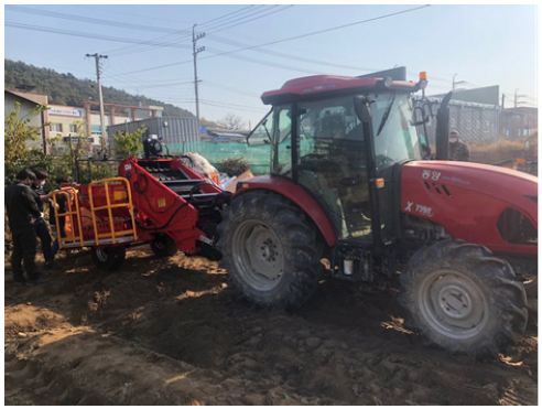
트랙터 부착형 땅속 작물 수확기에 발생하는 부하를 계측하기 위해 55 kW급 농업용 트랙터(TX76, TYM Co., Ltd., Iksan, Korea)를 사용하였으며 해당 트랙터는 Fig. 1과 같다. 계측용 트랙터의 크기는 4,002 mm (L) × 1,940 mm (W) × 2,624 mm (H) 이며, 무게는 2,865 kg이다. 트랙터의 엔진의 정격 출력은 2,200 rpm에서 55.4 kW이며, 싱크로셔틀 변속 방식을 적용하고 있다. 변속기는 전진 16단, 후진 16단의 변속 단수를 갖는다. 계측용 트랙터의 세부 제원은 Table 1과 같다.

http://dam.zipot.com:8080/sites/kjoas/images/N0030490418_image/Fig_KJOAS_49_04_18_F1.png

Fig. 1. A photo of agricultural tractor with underground crop harvester used in this study.

Table 1. Specification of a 41 kW class agricultural tractor for measurement used in this study.http://dam.zipot.com:8080/sites/kjoas/images/N0030490418_image/Table_KJOAS_49_04_18_T1.png

작업기는 땅속 작물 수확기(HD-PC900, Hyundae agricultural machinery Co., Ltd., Iksan, Korea)를 사용하였다. 땅속 작물 수확기의 크기는 3,750 mm (L) × 2,210 mm (W) × 1,375 mm (H) 이며, 작업 범위는 900 mm, 중량은 1,100 kg이다. PTO 작업 단수는 1단(540 rpm)에서 수행하였으며, 오일탱크 용량은 60 L이다. 유압 최대 압력은 130 bar이며, 최대 유압 온도는 70℃, 최저 유압 온도는 -5℃이다. 유압기어박스 오일은 SAE W 90을 사용하며, 기어박스 오일 용량은 0.3 L이다.

부하 계측 시스템

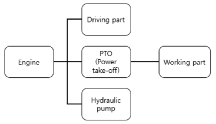
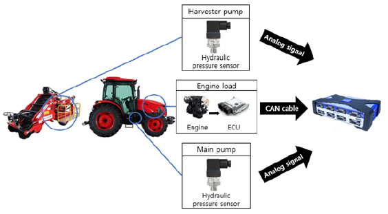
농작업 시 트랙터 엔진 동력은 Fig. 2와 같이 주행부, 유압부, PTO작업부로 전달된다. 계측 시스템은 Fig. 3과 같이 엔진, PTO, 유압의 소요동력을 측정하기 위해 구성하였다. 이 때, 구동 출력은 식(1)과 (2)를 이용하였으며 엔진 출력에서 PTO 출력 및 유압 출력의 차로 계산하였다. 유압 출력은 주유압 펌프와 보조 유압 펌프의 출력의 합으로 계산하였다.

Pdriving= Pengine − Phydraulic − PPTO (1)

Phydraulic= Pmain pump + Psub pump(2)

Where, Pdriving = Driving power (kW)

Pengine = Engine power (kW)

Phydraulic = Hydraulic power (kW)

PPTO = PTO power (kW)

Pmain pump = Main pump power (kW)

Psub pump = Sub pump power (kW)

디젤 엔진은 SAE (Society of Automotive Engineers)의 J1939를 CAN 통신 프로토콜로 사용한다. 따라서, J1939 규격의 프로토콜을 이용하여 엔진 토크 및 회전속도를 계측하였으며, 유압 펌프에는 최대 250 bar까지 측정 가능한 유압 센서(A-10, WIKA Alexander Wiegand SE & Co. KG, Bayern, Germany)를 장착하였다. 유압 센서는 최대 250 bar까지 측정할 수 있고, 오차는 ± 0.25% 이하, 유압 센서의 무게는 150 g 이하이다. 유압 출력은 식 (3)을 이용하여 계산하였으며, 계측된 압력 데이터와 제원을 이용하여 계산된 유량 데이터를 이용하였다.

http://dam.zipot.com:8080/sites/kjoas/images/N0030490418_image/Fig_KJOAS_49_04_18_F2.png

Fig. 2. Schematic diagram of power flow of tractor equipped underground crop harvester.

http://dam.zipot.com:8080/sites/kjoas/images/N0030490418_image/Fig_KJOAS_49_04_18_F3.png

Fig. 3. Schematic diagram of load measurement system of tractor equipped underground crop harvester during potato harvest operation. ECU, engine control unit; CAN, controller area network.

Phydraulic = ην × http://dam.zipot.com:8080/sites/kjoas/images/N0030490418_image/Eq_KJOAS_49_04_18_eq1.png (3)

Where, Phydraulic = Hydraulic power (kW)

ην = Volumetric efficiency (%)

P = Pressure of hydraulic system (bar)

Q = Flow rate of hydraulic system (cc·s-1)

PTO 출력은 수확기의 유압 펌프, 굴취부 유압 모터, 이송부 유압 모터 및 톤마대 적재 실린더 제어 밸브로 전달되므로 각 요소에 유압 센서를 설치하여 측정하고 계산하였다. 데이터 수집 장치(QuantumX 840B, HBM, Darmstadt, Germany)를 계측 시스템 개발에 사용했으며, 데이터 수집장치는 최대 40 kHz까지 계측 가능하며, 정확도 등급은 0.05, 작동 온도범위는 -20℃에서 65℃, 채널 수는 8개이다.

필드 테스트

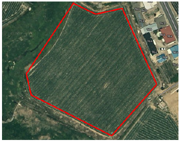
필드 테스트는 Fig. 4에 나타난 경북 고령군 개진면에 위치한 필드에서 감자를 대상으로 수행하였다. 작업 속도조건은 1 km·h-1 내외로 실제 작업 간 사용하는 속도로 설정하였으며, 신뢰성 확보를 위해 농작업에 숙련된 운전자가 운전하였다.

http://dam.zipot.com:8080/sites/kjoas/images/N0030490418_image/Fig_KJOAS_49_04_18_F4.png

Fig. 4. A photo of field test location used in this study.

필드시험은 수확-선회-수확-선회의 순서로 수행하였으며, 20 - 50 sec는 수확 작업, 50 - 55 sec는 선회 작업, 55 - 60 sec는 수확 작업, 60 - 100 sec는 선회 작업의 데이터를 나타낸다. 또한 반복 작업 간 1회의 수확 작업을 하나의 구간으로 설정하였다.

Results and Discussion

엔진 데이터

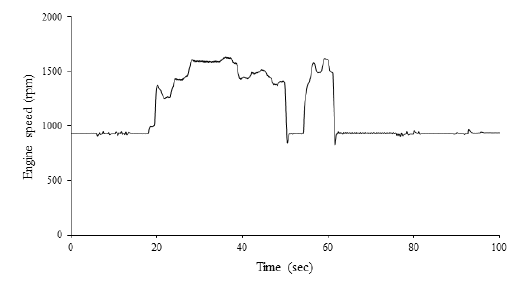
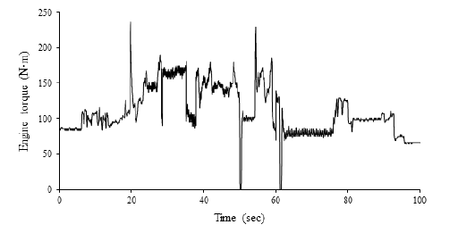
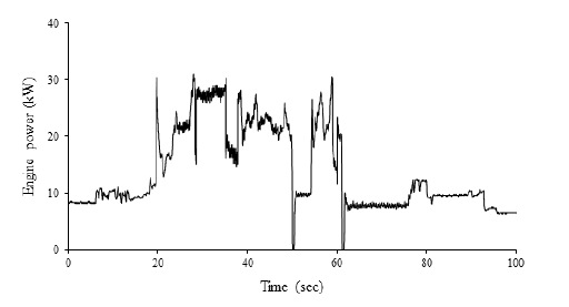
땅속작물 수확 작업 시 엔진 회전속도 데이터는 Fig. 5와 같이 나타났으며, 작업구간에서 엔진 회전속도는 845 - 1,633 rpm의 범위로 나타났다. 엔진 토크 데이터는 Fig. 6과 같이 나타났으며, 엔진 토크는 95 - 228 Nm의 범위로 나타났다. 엔진 출력 데이터는 Fig. 7과 같이 나타났으며, 엔진 출력은 9 - 31 kW의 범위로 나타났다. 해당 데이터는 엔진 정격 출력의 약 16 - 36%에 해당하는 것으로 나타났으며, 상세 엔진 데이터는 Table 2와 같다.

유압 펌프 데이터

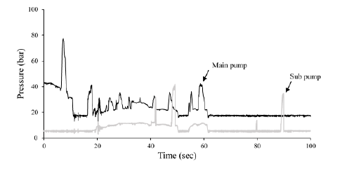
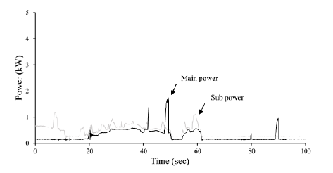
작업 간 트랙터 주유압 및 보조유압 펌프 데이터는 Fig. 8과 같이 나타났으며, 주유압 펌프의 유압은 3 - 41 bar의 범위로, 보조유압 펌프의 유압은 12 - 42 bar의 범위로 나타났다. 주유압 및 보조유압 펌프 출력 데이터는 Fig. 9와 같이 나타났으며, 주유압 펌프의 출력은 0.1 - 1.7 kW의 범위로, 보조유압 펌프의 출력은 0.2 - 1.1 kW의 범위로 나타났다. 상세 유압 펌프 데이터는 Table 3과 같다.

http://dam.zipot.com:8080/sites/kjoas/images/N0030490418_image/Fig_KJOAS_49_04_18_F5.png

Fig. 5. Result of measured engine speed data of tractor equipped underground crop harvester during potato harvest operation.

http://dam.zipot.com:8080/sites/kjoas/images/N0030490418_image/Fig_KJOAS_49_04_18_F6.png

Fig. 6. Result of measured engine torque data of tractor equipped underground crop harvester during potato harvest operation.

http://dam.zipot.com:8080/sites/kjoas/images/N0030490418_image/Fig_KJOAS_49_04_18_F7.png

Fig. 7. Result of measured engine power data of tractor equipped underground crop harvester during potato harvest operation.

Table 2. Results of averaged measured engine data of tractor during potato harvesting operation.http://dam.zipot.com:8080/sites/kjoas/images/N0030490418_image/Table_KJOAS_49_04_18_T2.png
http://dam.zipot.com:8080/sites/kjoas/images/N0030490418_image/Fig_KJOAS_49_04_18_F8.png

Fig. 8. Results of measured tractor hydraulic pump pressure data of tractor equipped underground crop harvester during potato harvest operation.

http://dam.zipot.com:8080/sites/kjoas/images/N0030490418_image/Fig_KJOAS_49_04_18_F9.png

Fig. 9. Results of measured tractor hydraulic pump power data of tractor equipped underground crop harvester during potato harvest operation.

Table 3. Results of averaged measured hydraulic pump data of tractor during potato harvesting operation.http://dam.zipot.com:8080/sites/kjoas/images/N0030490418_image/Table_KJOAS_49_04_18_T3.png

수확기 유압모터 데이터

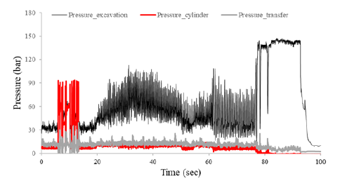
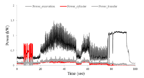
작업 간 수확기의 굴취부 유압모터의 유압 데이터는 Fig. 10과 같이 나타났으며, 유압모터의 유압은 24 - 112 bar의 범위를 보였다. 톤마대 실린더 밸브의 유압은 7 - 14 bar의 범위를 보였다. 이송부 유압모터의 유압은 7 - 25 bar의 범위를 보였다. 수확기의 굴취부 유압모터의 출력 데이터는 Fig. 11과 같이 나타났으며, 유압모터의 출력은 0.2 - 1.5 kW의 범위를 보였다. 톤마대 실린더 밸브 출력은 0.1 - 0.2 kW의 범위를 보였다. 이송부 유압모터의 출력은 0.1 - 0.3 kW의 범위를 보였다. 상세 굴취부 유압모터 데이터는 Table 4와 같다.

http://dam.zipot.com:8080/sites/kjoas/images/N0030490418_image/Fig_KJOAS_49_04_18_F10.png

Fig. 10. Results of measured hydraulic pressure data of hydraulic motor of the excavation part of tractor equipped underground crop harvester during potato harvest operation.

http://dam.zipot.com:8080/sites/kjoas/images/N0030490418_image/Fig_KJOAS_49_04_18_F11.png

Fig. 11. Results of measured power data of hydraulic motor of the excavation part of tractor equipped underground crop harvester during potato harvest operation.

Table 4. Results of averaged measured hydraulic motor data of excavator during potato harvesting operation.http://dam.zipot.com:8080/sites/kjoas/images/N0030490418_image/Table_KJOAS_49_04_18_T4.png

구동 출력

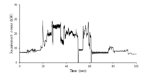
구동 출력은 엔진 출력에서 작업 간 트랙터의 유압 펌프 출력과 PTO 출력의 차로 계산하였으며 Fig. 12와 같이 나타났다. 해당 출력은 차량을 움직이기 위한 최소 필요한 구동 출력으로 판단된다. 구동 출력은 9 - 28 kW의 범위로 나타났으며, 상세 구동출력 데이터는 Table 5와 같다. 구동 출력은 작업 간 최대 30 kW미만으로 나타났으며, 해당 데이터를 기반으로 자주식 땅속 작물 수확기의 주행부 유압시스템의 제원 선정이 가능할 것으로 판단된다.

http://dam.zipot.com:8080/sites/kjoas/images/N0030490418_image/Fig_KJOAS_49_04_18_F12.png

Fig. 12. Result of measured requirement power of self-propelled underground crop harvester during potato harvest operation.

Table 5. Results of calculated averaged traction power data of tractor equipped underground crop harvester during potato harvesting operation.http://dam.zipot.com:8080/sites/kjoas/images/N0030490418_image/Table_KJOAS_49_04_18_T5.png

Conclusion

국내 농업 환경에 적합한 자주식 땅속 작물 수확기 개발을 위한 기초 연구로써, 기존의 트랙터 부착형 땅속 작물 수확기에 부하 계측 시스템을 구축하고 수확 작업 시 발생하는 엔진, 유압, PTO 데이터를 계측하고 소요 동력을 계산하였다. 55 kW급 트랙터를 이용하여 필드 테스트를 수행하였으며, 유압펌프, 굴취부 유압모터, 이송부 유압모터 및 톤마대 적재 실린더 제어 밸브에 각각 유압센서를 설치하였다. 필드 테스트는 PTO 1단 조건에서 감자 수확 작업을 대상으로 수행하였다.

필드 테스트 결과, 작업구간에서 엔진 회전속도, 토크, 출력은 각각 845 - 1,633 rpm, 95 - 228 Nm, 9 - 31 kW의 범위로 나타났다. 구동출력은 작업 간 엔진 출력에서 트랙터의 유압펌프와 PTO 출력을 제외함으로써 계산되었으며, 해당 출력은 차량을 움직이기 위한 최소 소요 동력으로 판단된다. 구동출력은 9 - 28 kW의 범위를 보였으며 이는 엔진 정격출력 대비 16.2 - 50%를 차지하는 것으로 판단된다. 따라서, 해당 출력을 고려한 엔진 동력원 선정이 요구된다. 주유압 및 보조유압 펌프의 유압은 각각 3 - 41, 12 - 42 bar의 범위를 보였으며, 주유압 및 보조유압 펌프의 출력은 각각 0.1 - 1.7, 0.2 - 1.1 kW의 범위로 나타났다. 상세 계측 데이터의 평균 값은 Table 6과 같다. 작업 간 수확기의 굴취부 유압모터, 톤마대 실린더 밸브, 이송부 유압모터의 유압은 각각 24 - 112, 7 - 14, 7 - 25 bar의 범위를 보였으며 수확기의 굴취부 유압모터, 톤마대 실린더 밸브, 이송부 유압모터의 출력은 각각 0.2 - 1.5, 0.1 - 0.2, 0.1 - 0.3 kW의 범위를 보였다. 추후 땅속 작물 수확기를 개발하기 위한 부품을 선정할 시, 본 연구에서 계측한 데이터를 고려하여 부품 선정이 가능할 것으로 판단된다.

본 연구는 일반적인 수확 작업 속도인 1 km·h-1의 일정한 속도로 수행하였으며, 기어 단수에 대한 고려는 배제되었다. 따라서 향후 연구에서는 동력전달 시스템 검증 및 수확 작업 시 사용되는 기어 단수에 따른 부하 계측을 수행하는 것이 필요할 것으로 판단된다.

Table 6. Results of averaged requirement power of tractor equipped underground crop harvester during potato harvesting operation.http://dam.zipot.com:8080/sites/kjoas/images/N0030490418_image/Table_KJOAS_49_04_18_T6.png

Conflict of Interests

No potential conflict of interest relevant to this article was reported.

Acknowledgements

본 논문은 농림축산식품부의 재원으로 농림식품기술기획평가원의 기술사업화지원사업(122033-2)과 첨단농기계산업화기술개발사업(321062-02)의 지원을 받아 연구되었음.

References

1 Baek SM, Kim WS, Baek SY, Jeon HH, Lee JH, Song YI, Choi Y, Kim YK, Lee SH, Kim YJ. 2021. Analysis of the power requirements of a 55 kW class agricultural tractor during a garlic harvesting operation. Korean Journal of Agricultural Science 48:1039-1050. [in Korean]  

2 Jang JH, Kim WS, Choi CH, Park SU, Kim YJ. 2018. Analysis of power requirement of the underground crop harvester attached on agricultural tractor during traction operation. The Journal of Korea Institute of Information, Electronics, and Communication Technology 11:150-155. [in Korean]  

3 Kim WS, Lee WS, Kim YJ. 2020. A review of the applications of the Internet of things (IoT) for agricultural automation. Journal of Biosystems Engineering 45:385-400.  

4 KOSIS (Korean Statistical Information Service). 2021a. Mechanization rate of rice (harvest) operation. KOSIS, Daejeon, Korea. [in Korean]  

5 KOSIS (Korean Statistical Information Service). 2021b. Mechanization rate of field crop (harvest) operation. KOSIS, Daejeon, Korea. [in Korean]  

6 Lee SH, Kang TG, Choi Y, Kang YK, Kim YH. 2020. Performance analysis of a gathering type potato harvester. Journal of Agriculture & Life Science 54:94-100. [in Korean]  

7 Lim H, Seo MK, Joo YH, Yun BU, Bang BJ. 2019. Development of an intelligent control system for a underground crop harvester. The Transactions of the Korean Institute of Electrical Engineers 68:173-179. [in Korean]  

8 Suh DS. 2021. Promotion of ‘Field Crop Mechanization’ emerged with COVID 19. Accessed in https://www.krei.re.kr/krei/selectBbsNttView.do?key=109&bbsNo=75&nttNo=147909&searchCtgry=&searchCnd=all&searchKrwd=&pageIndex=7&integrDeptCode= on 6 October 2022. [in Korean]